Table of Contents (click to expand)
A resistor is a passive two-terminal component that adds a fixed amount of electrical resistance to a circuit. It is used to limit current, divide voltage and adjust signal levels. The voltage across a resistor is proportional to the current through it, set by Ohm's law (V = I × R).
Whether you are someone who has had decent exposure to electronics or possess a four-year baccalaureate in Electrical Engineering, wherever you lie on this spectrum, you have at least come across the word “resistor”. The name of this electronic element gives away its functionality. However, do you know how a resistor works and its different applications and purposes? If you don’t, not to fear. First, let’s take a look at the theory of operation of a resistor.
Theory Of Operation
A resistor is considered to be a passive two-terminal element that introduces a certain level of resistance into the electrical circuit. The primary roles that a resistor plays in any given electrical circuit are to reduce the flow of current, divide voltage level and adjust the signals, among many other uses.
V = I × R
The fundamental electrical law known as Ohm's Law is deeply connected to resistors. This is because the behavior of an ideal resistor is dictated entirely by Ohm's law, which is written as follows:
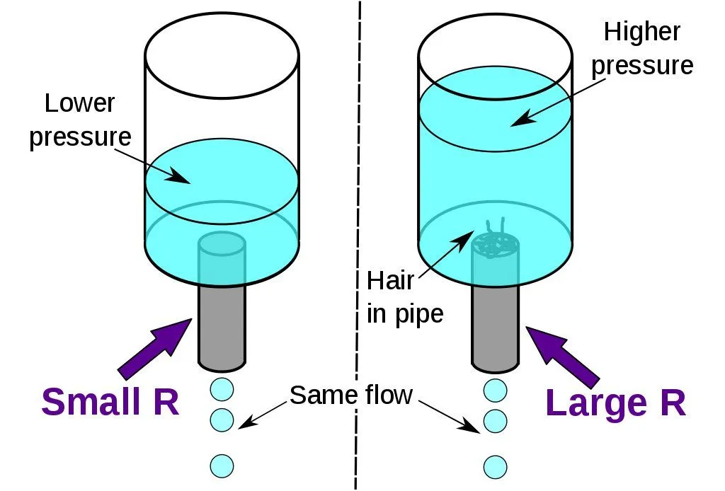
Ohm's Law states that the voltage across a resistor is proportional to the current flowing through it, where the resistance R is the constant of proportionality. Another practical way to visualize this is to compare the electric current with a hydraulic analogy. Let’s assume a tank that has a clogged pipe. The clogged pipe has a smaller pathway for the water to flow. This means that the amount of force required for the water to flow out of the pipe is more significant. However, if the pipe were not clogged, then the water would flow through smoothly. This can be similarly compared to a resistor with a high level of resistance. In that case, the voltage required to push a certain amount of current would be higher than for a resistor with lower resistance, in which case less voltage is needed to move the same amount of current.
Types Of Connections
Now that we have some idea as to how an individual resistor works concerning voltage and current, let’s take a look at how a specific connection of a certain number of resistors behaves. There are two fundamental connections in which electrical components are connected within the circuit: series and parallel.
Resistors In Series
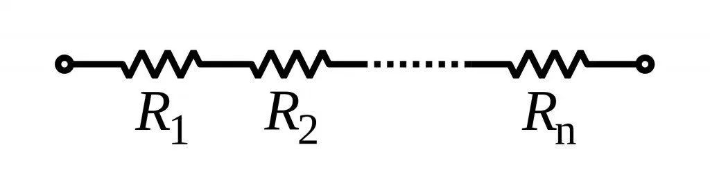
A series circuit also has other names, such as current-coupled or daisy-chained. The current in a series circuit passes through every part (or component) of the circuit. Therefore, we can safely conclude as a rule of thumb that all resistors in a series connection have the same current flowing through them. The main characteristic of a series circuit is that it has only one path through which the electric current can flow. If there is an opening or broken section in any part of the circuit, it causes the entire circuit to stop working. To provide a classic example, let’s take the case of Christmas lights. Even if one of the bulbs’ fuses goes out or is removed, the entire chain of bulbs stops working.

Resistors In Parallel
In the case of a parallel circuit, there are two or more components that are connected in parallel with one another. In such a case, the potential difference across all the resistors connected in parallel will be the same, and they also have identical polarities. The current, however, is calculated differently. The total current is the sum of the currents flowing through the individual resistors in an electrical circuit. The advantage that parallel connections in a circuit have is that even if one of the components of the circuit must be taken out or has stopped working, the entire circuit can continue to work.


Resistor Color Codes And Types
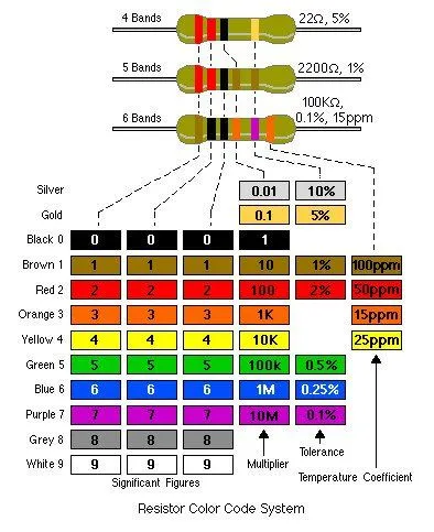
If you’ve ever picked up an axial lead resistor, you have likely observed a band of colors around it. Those colored bands are in place to impart vital information about the resistor:
- The first band indicates the first significant digit of the resistance value.
- The second band indicates the second significant digit of the resistance value.
- The third band is the multiplier, the power of ten by which the first two digits are multiplied.
- The fourth band indicates the tolerance, the percentage by which the actual resistance may differ from the stated value (for example, ±5%).
- Higher-precision resistors add a fifth band: this gives a third significant digit, so the multiplier shifts to the fourth band and the tolerance to the fifth. A six-band resistor adds one more band for the temperature coefficient, measured in ppm/K.
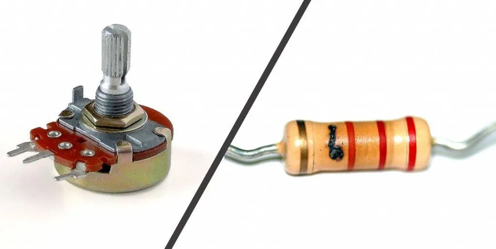 Resistors come in different forms, broadly split into fixed and variable resistors. Fixed resistors have a resistance that is set during manufacture and does not change over time; for example, the axial metal resistor shown above. Variable resistors are those whose resistance can be adjusted within a certain range. The classic example of a variable resistor is a potentiometer. A potentiometer is a three-terminal resistor with a sliding or rotating contact that forms an adjustable voltage divider. If only two terminals are used (one end and the wiper), it acts as a variable resistor or rheostat. In short, resistors are a fundamental electronic component found in almost every electrical circuit.