Table of Contents (click to expand)
A multimeter is a single instrument that measures voltage (AC and DC), current, and resistance. It works as a voltmeter wired in parallel, an ammeter wired in series, and an ohmmeter that pushes a known current through a component and reads the voltage drop, applying Ohm’s law (V = IR) to display the result.
When it comes to gauges, scales and meters, they are usually primed to measure a few parameters at the most. However, what if there was a meter that could measure multiple parameters? This is where the multimeter steps in. A multimeter is an instrument widely used by electrical engineers and serves a broad spectrum of functions. There’s a multimeter for every occasion, from DIY electronic projects to high-voltage engineering. Now, let’s take a look at the details of a multimeter’s operation.
What Does A Multimeter Measure?
Before we open up the instrument, it helps to know what those three core functions actually do. Every multimeter, whether it costs $15 or $1,500, is built around three basic measurements: voltage, current, and resistance. The clever part is that the way it connects to your circuit changes completely depending on which one you’re reading.
To measure voltage, the multimeter acts as a voltmeter and is connected in parallel, with one probe on each side of the component you’re testing. Voltage is the difference in electrical pressure between two points, so you always need two points to compare. The catch is that the meter shouldn’t steal current away from the circuit and skew the reading, so a voltmeter is built with very high input impedance, typically around 10 megohms (10 MΩ) on a handheld digital meter. With so little current flowing through it, the meter sees the voltage but barely disturbs the circuit. Multimeters read both DC voltage (a steady battery, for example) and AC voltage (such as household mains).
To measure current, the multimeter becomes an ammeter and is wired in series, meaning you have to break the circuit and route the current straight through the meter. Here the requirement is the opposite of the voltmeter: an ammeter needs very low resistance so it adds almost nothing to the circuit it’s measuring. This is also why connecting a meter set to “amps” straight across a battery is a classic way to blow its internal fuse: with hardly any resistance in the path, a large current rushes through.
To measure resistance, the multimeter works as an ohmmeter. It uses its own internal battery to push a small, known current through the component and then measures the resulting voltage drop. From those two figures it works out the resistance using Ohm’s law, V = IR (rearranged to R = V ÷ I), and shows the answer in ohms (Ω). Because the meter supplies its own current, resistance is always measured on a circuit with the power switched off.
Most multimeters add a handy fourth trick: a continuity test. This is really just a resistance measurement with a buzzer attached. When the meter detects a near-zero resistance path (a few ohms or less) between its probes, it beeps, telling you the two points are electrically connected. It’s the fastest way to check whether a wire is intact, a fuse is good, or a solder joint is actually joined, all without taking your eyes off your hands.
Operation Of A Multimeter
A multimeter is not just a single device. It is a combination of a multi-range DC voltmeter, multi-range AC voltmeter, multi-range ammeter, and multi-range ohmmeter. It’s packed to the brim with all the necessary parts of this configuration. When it comes to the analog multimeter, DC voltage is measured with a series resistor connected between the meter movement and the circuit under test. A switch that is usually of a rotary type, which allows greater resistance to being inserted, is in series with the meter movement to read higher voltages. Obtaining the full-scale voltage for the entire range is done by calculating the product of the basic full-scale deflection current of the movement, and the sum of the series resistance and the movement’s resistance.
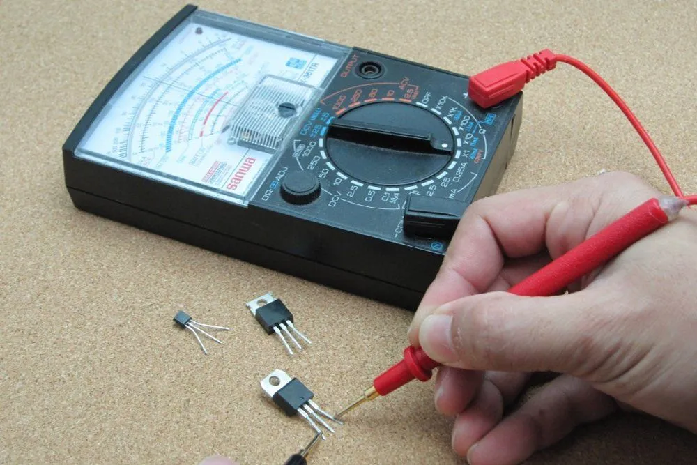
When it comes to the measurements of resistance, there is a battery present in the multimeter that passes current through the measurement coil. The current available depends on the charge of the battery, which changes over time; a multimeter usually has an adjustment for the ohm scale to zero it. The ohm’s scale is compressed, so the resolution is better at lower resistance values. Amplified instruments simplify the design of the series and shunt resistor networks. The internal resistance of the coil is decoupled from the selection of the series and shunt range resistors; the series network thus becomes a voltage divider. Where AC measurements are required, the rectifier can be placed after the amplifier stage, improving precision at low range.
Analog Multimeter And Digital Multimeter
For analog multimeters, current ranges, matched low-resistance shunts are connected in parallel with the meter movement to divert most of the current around the coil. Moving coil instruments can respond only to the average value of the current through them. To measure alternating current, which oscillates repeatedly, a rectifier is inserted in the circuit so that each negative half cycle is inverted; the result is a varying and nonzero DC voltage with a maximum value that is half the AC peak to peak voltage, assuming a symmetrical waveform. Since the rectified average value and the root mean square (RMS) value of a waveform are only the same for a square wave, simple rectifier-type circuits can only be calibrated for sinusoidal waveforms. Other wave shapes require a different calibration factor to relate RMS and average value. This type of circuit usually has a fairly limited frequency range. Since practical rectifiers have a non-zero voltage drop, their accuracy and sensitivity are poor at low AC voltage values.
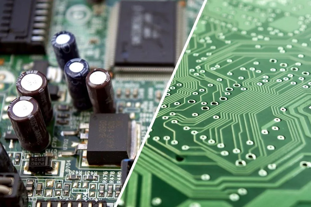
Digital multimeters incorporate amplifiers, which use the same principles as analog multimeters for resistance readings. For resistance measurements, a small constant current is usually passed through the device being tested, and the digital multimeter reads the resultant voltage drop; this eliminates the scale compression found in analog meters, but requires a source of precise current. An auto-ranging digital multimeter can automatically adjust the scaling network, so the measurement circuits use the full precision of the A/D converter. In all types of multimeters, the quality of the switching elements is critical to stable and accurate measurements. The best DMMs use gold-plated contacts in their switches; less expensive meters use nickel plating or none at all, relying on printed circuit board solder traces for the contacts. Accuracy and stability (e.g., temperature variation, or aging, or voltage/current history) of a meter’s internal resistors (and other components) is a limiting factor in the long-term accuracy and precision of the instrument. For these reasons, the multimeter is one of the most versatile measuring tools used by electrical and electronics engineers around the world!