Table of Contents (click to expand)
A rectifier converts the AC to DC and then passes it to the device’s core circuit. A rectifier can generate a DC supply either by rectifying only one cycle (either positive or negative) of the AC supply or by rectifying both of them. The former is therefore called a half-wave rectifier, as it only rectifies one half of the supply waveform, while the latter is called a full-wave rectifier, as it rectifies both halves or the entirety of the waveform.
To begin with, your most prized possession would be unable to function without a rectifier: no, it’s not your phone, but its charger. Your phone charger and, for that matter, the majority of your household electronic devices do not operate on an AC supply – the alternating current generated by power plants and then supplied to your house via transmission cables, but rather on a DC supply: a constant current that flows unfailingly in a single direction.
The rectifier is a circuit embedded in your device that converts the restless AC supply coming to your house into a steady DC supply, so that your devices can function properly. However, how does the rectifier achieve this rectification?
The Diode
The diode is one of the semiconductor revolution’s first offspring. The device is basically two slabs of semiconductors glued to each other. However, the semiconductors differ in their properties: one is electron-impoverished, or exhibits an excess of positive charges or holes, while the other is suffused with electrons and therefore exhibits an excess of negative charges. Together, they constitute what is called a PN Junction.
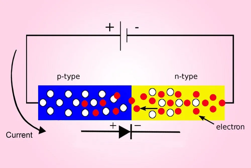
The fundamental purpose of a diode, unlike a resistor, is to allow current to flow in a single direction. Current through a diode will only flow when its positive semiconductor, or the anode, is connected to the positive terminal of the battery, and its negative semiconductor, or the cathode, is connected to the negative terminal of the battery. The current is stifled when the terminals are cross-connected.
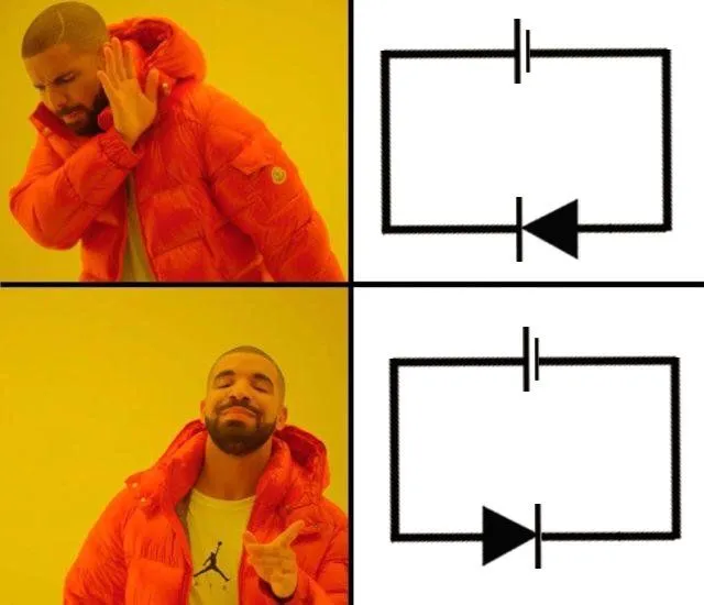
The diode lies at the heart of the rectifier, where the rectifier leverages its properties to fulfill its purpose.
Rectification
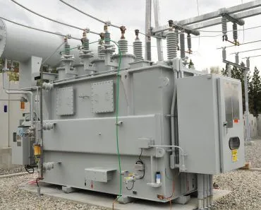
First of all, the AC voltage is drastically reduced, as a triple-digit voltage will fry your toaster or charger. This is achieved with a transformer or a voltage regulator. The diminished AC supply is then fed to the device, where it is first greeted by the rectifier. The rectifier converts the AC to DC and then passes it to the device’s core circuit.
A rectifier can generate a DC supply either by rectifying only one cycle (either positive or negative) of the AC supply or by rectifying both of them. The former is therefore called a half-wave rectifier, as it only rectifies one half of the supply waveform, while the latter is called a full-wave rectifier, as it rectifies both halves or the entirety of the waveform.
Half Wave Rectifier
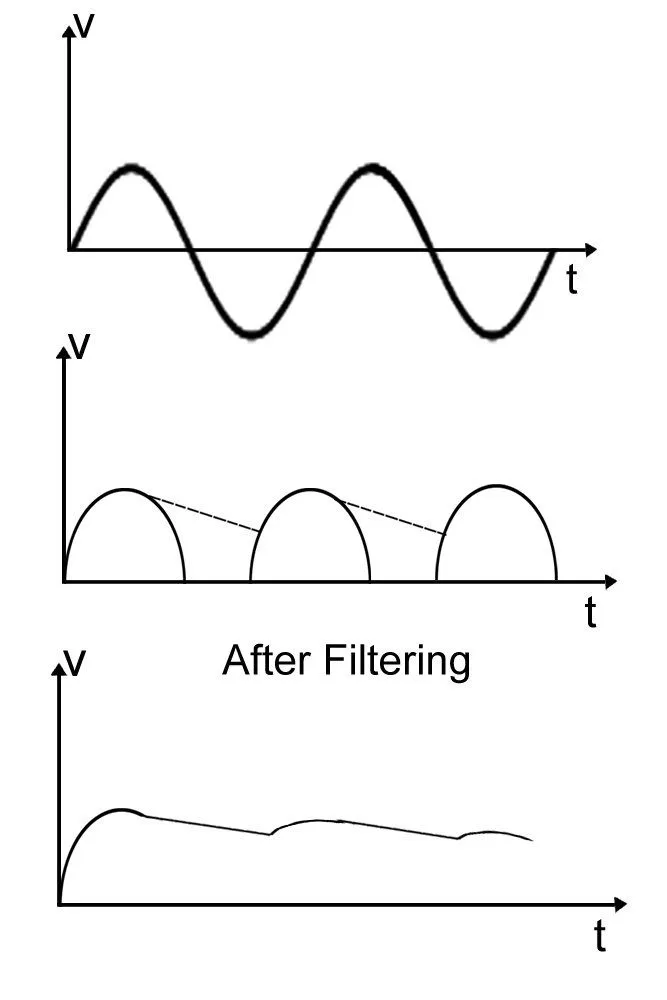
The magnitude of the AC supply is reduced with a transformer and fed to this particular configuration of diodes. The configuration will rectify only the positive cycles of the waveform:
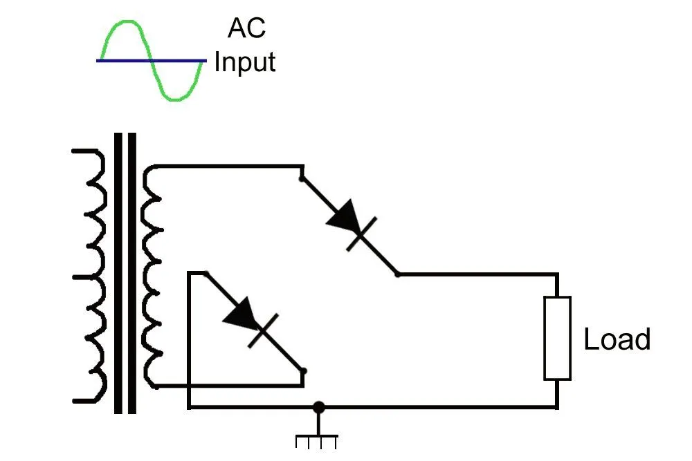
During a positive cycle, a positive charge is obtained on the upper node, while a negative charge is obtained on the lower node. Now, because a diode will allow the current to pass only when the anode (the triangle) is connected to the positive terminal and the cathode (the stick) is connected to the negative terminal, both the diodes in the configuration will conduct during the positive cycle. The load is therefore supplied with a current: the positive cycle is replicated on its output waveform.
However, when the AC supply alternates, the polarity on the nodes swap: now, the upper node is negatively charged, while the lower node is positively charged. The diodes are cross-connected and the current ceases to flow. When no current reaches the load, the output waveform for the negative cycle is a line tracing the X-axis, depicting the passage of time, but not any current.
The negative cycle can be rectified (at the cost of the positive cycle, of course) through some tinkering with the configuration of the diodes:
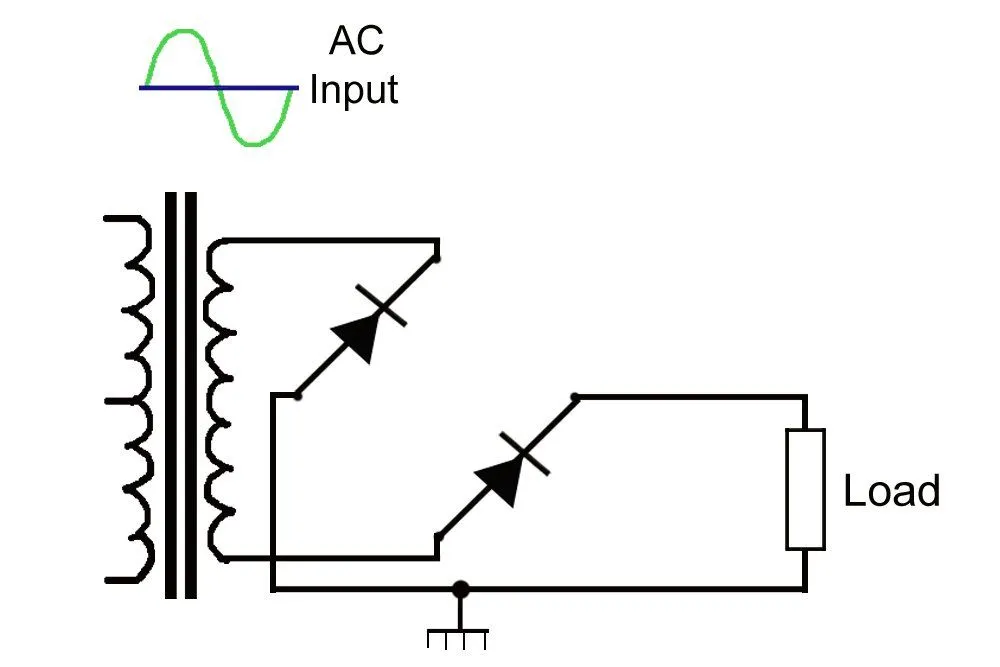
The configuration is such that the load will experience a current during the negative cycle, more specifically, when a negative charge is obtained on the upper node and a positive charge is obtained on the lower node. Of course, being a half-wave rectifier, the current is stifled when the current alternates and the polarities swap. As this rectifier only rectifies the negative cycles, its output waveform will look like this:
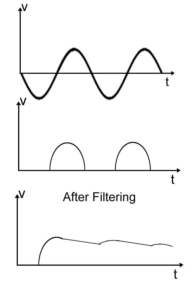
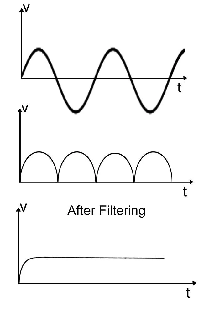
However, one can observe how the waveforms are bumpy: two waves of productivity separated by an undesirable void of idleness or unproductivity. The waveform can be “smoothed” with a large, filtering capacitor. The capacitor will accumulate energy during the productive cycle and release it during the unproductive cycle until the next productive cycle begins. It then reaccumulates energy and the whole cycle repeats. The result is a bridging of the valley – a constant, unidirectional DC supply.
Still, the conversion is dramatically inefficient: why must we waste half of all the energy? Why shouldn’t we utilize every ounce of it?
Full Wave Rectifier
One rectifier rectifies only the positive halves, while another rectifies only the negative halves. So how do we develop a rectifier that rectifies both halves sequentially? Simply by combining the two rectifiers!
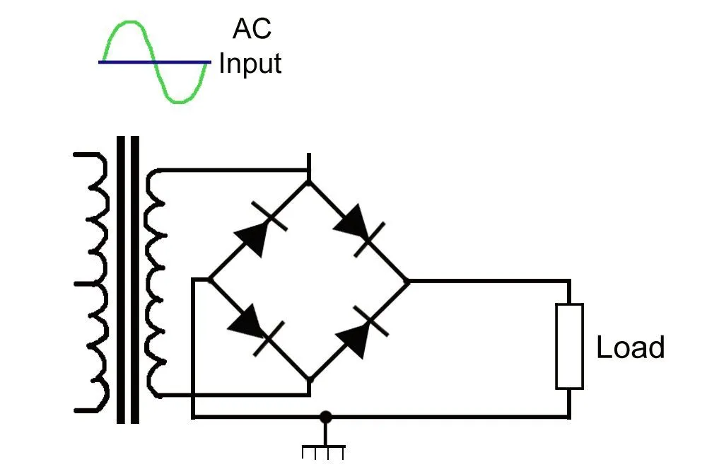
The circuit appears enmeshed and therefore automatically complex and confusing. However, its function, on the contrary, is astonishingly simple. Examine the circuit carefully and you’ll observe that it is literally a combination of the two half-wave rectifiers explained above.
The first half-wave rectifier conducts during the positive cycle, while the second half-wave rectifier conducts during the negative cycle. As the current passes through the load during both cycles, no voids are found in the output waveform. It is a continuous series of hills, or trail of energy.
Of course, gaps do exist between the hills, but they are much narrower than the gaps in the output waveform of a half-wave rectifier. We can remove these small inconsistencies, again, with a large filtering capacitor. The smoothed waveform is an even steadier, energy-efficient and high-quality DC supply.
The Bridge Rectifier
The full-wave rectifier described above does the job, but it carries an awkward requirement: it leans on a transformer with a center tap, an extra wire pulled out from the middle of the secondary winding. That means more copper, more weight and more cost. Engineers wanted the same both-halves output without paying that toll, and the answer is the bridge rectifier.

Instead of two diodes fed by a split winding, the bridge uses four diodes arranged in a diamond, or "bridge", across a plain two-wire AC input. The clever part is that the diodes work in pairs. During the positive half-cycle, one diagonal pair is forward-biased and conducts, steering current through the load in a fixed direction. When the supply flips to its negative half-cycle, those two switch off and the other diagonal pair takes over, but it routes the current through the load in exactly the same direction as before. Only two of the four diodes ever conduct at once, and the load never notices that the input reversed.
The payoff is that no center-tapped transformer is needed, which makes the bridge cheaper and lighter than the two-diode design for the same full-wave result. That efficiency is why the four-diode bridge, patented by Karol Pollak in 1895 and independently devised by Leo Graetz in 1897 (hence its other name, the "Graetz circuit"), is the arrangement hiding inside most of the power adapters on your desk. The one price you pay is that the current always flows through two diodes in series rather than one, so a little more voltage is lost as heat along the way.
What Are Rectifiers Used For?
Rectifiers are so common that we mostly forget they exist. Their headline job is the one we have been describing all along: turning an AC supply into the DC that electronics actually run on. Every phone charger, laptop brick, television and LED driver contains a rectifier at the front of its power supply, and the same circuit does the heavy lifting whenever a battery is charged from the mains.

The uses reach well beyond your power outlets, though. In an old AM radio, a rectifier acts as a detector, stripping the audio signal off the high-frequency carrier wave so that you can actually hear it. Welding machines use rectifiers to deliver a steady, polarized DC arc. Electric trains and trams rely on them (often built from thyristors, a controllable cousin of the diode) to feed and finely control their traction motors. And at the largest scale of all, high-voltage direct current (HVDC) transmission lines use banks of rectifiers to convert AC into DC for shipping bulk power efficiently across hundreds of kilometers.
The device pictured above is a mercury-arc rectifier, a glowing glass-and-metal ancestor that handled these high-power jobs for much of the twentieth century. Before it, engineers even used noisy mechanical switches; then came vacuum-tube diodes, first built for power supplies by Saul Dushman at General Electric in 1915. Every one of them has now been quietly replaced by the humble silicon diode, which does the same work with no moving parts, no vacuum and no glow.
What Does A Regulator Rectifier Do?
If you ride a motorcycle, you have probably heard mechanics mention the "reg/rec", short for the regulator rectifier. It is a single potted unit that does two jobs at once. A motorcycle's engine spins an alternator that generates AC, but the bike's battery and electronics need DC, so the rectifier half converts that alternating current into direct current, exactly as the diodes in this article do.
The regulator half then solves a second problem. An engine's speed swings wildly between idling at a traffic light and racing down a highway, and the alternator's raw output climbs right along with the revs. Left unchecked, that rising voltage would boil the battery and cook the electrical system. The regulator caps the charging voltage at a safe level (typically around 14.5 volts) by diverting, or "shunting", the surplus energy to ground, where it is dumped as heat. This is also why a failed reg/rec is a common motorcycle complaint: when it dies, the battery either stops charging or slowly gets overcharged. A "transformer rectifier" performs the same AC-to-DC role at a larger industrial scale, pairing a step-down transformer with a rectifier inside one housing.