Table of Contents (click to expand)
An induction motor works by passing alternating current through stator electromagnets to create a rotating magnetic field. That field induces a current in the rotor, which produces its own opposing field. The two fields interact and drag the rotor around, always slightly slower than the field (a lag called slip), which is why it is also called an asynchronous motor.
Today, we flick a switch and get instant power, but our ancestors would have considered that a miracle. We know that it runs because it’s powered by a motor, but it’s still incredibly impressive! On that note, you can find motors in all forms of devices and machinery that move. Have you ever thought about how many electric motors are in the room you’re sitting in right now? Well, two for starters: one in your hard drive and another in your cooling fan. In your house, you’ll find additional motors in hair dryers and many toys; in the bathroom, they’re in extractor fans and electric shavers, and in the kitchen, motors are in just about every appliance you can name, from washing machines and dishwashers to coffee grinders, microwaves, and electric can openers. Electric motors have proven themselves to be among the greatest inventions of all time. Now, let’s pull some apart and find out how they work!
The Theory Behind Motors
An electric motor works on a very simple principle. If you pass electricity to one end of the motor axle, it rotates at the other end, which provides the power to drive a machine. One might wonder at this junction: how did this electricity lead to movement? To understand the mechanism behind this phenomenon, let’s take an ordinary wire and then loop and lay it between the poles of two permanent magnets. If you connect the ends of the loop to a battery, you will see that the wire will momentarily jump. This might sound perplexing, but it’s based on a very fundamental scientific principle. This phenomenon occurs because, when the electric current passes through the wire, a momentary magnetic field is generated around the wire. When this momentary magnetic field is produced, it interacts with the magnetic fields of the permanent magnet. And as we know, one of two things occurs when two magnetic fields are generated: they either attract or repel. This is what makes the wire jump.
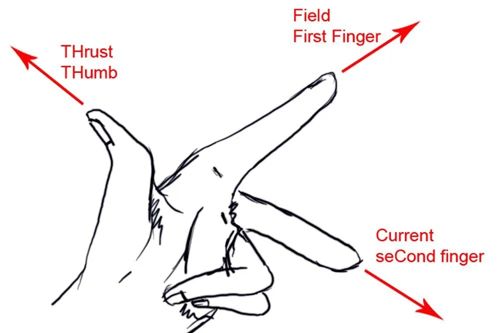
To go a step further, we can even predict the motion of the conductor (in the above case, the wire). This can be done by the Fleming Left Hand Rule (also known as the motor rule). To use this rule, stick out your thumb, index and middle fingers in such a way that each of the fingers is perpendicular to one another. Each finger signifies a particular force. The index finger indicates the direction of the magnetic field of the permanent magnets. The middle finger stands for the direction of the flow of the current in the conductor. Your thumb then points in the direction the conductor moves. An easy way to remember it: Forefinger for Field, seCond finger for Current, and thuMb for Motion.
Design Of An Induction Motor
Motors of all kinds are based on the same basic principles, the only difference in an induction motor being that the wire is bent into a rectangular form. A common occurrence that might occur in the wire is that it would move ninety degrees and then flip the wire back to its original position. This is not acceptable when we require constant rotations in a particular direction, but this can be overcome with the help of the commutator. The primary job of the commutator is to flip the current every time the wire rotates ninety degrees, which ensures that the wire keeps rotating in the same direction.
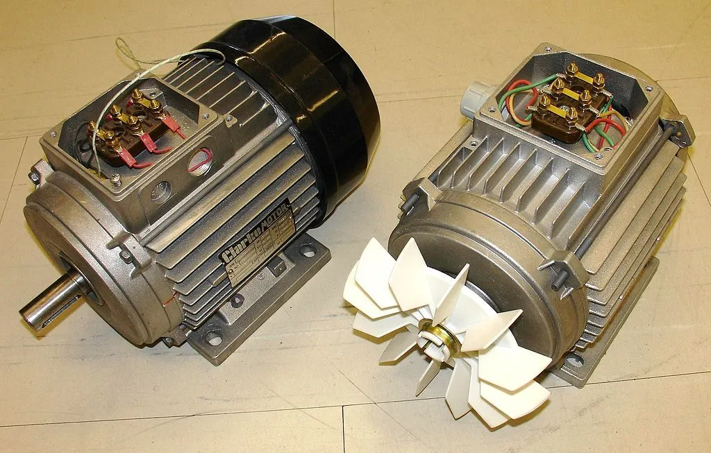
Until now, we’ve seen the primary design of the DC motor. An induction motor, on the other hand, has a slightly different design than a DC motor. When it comes to an AC motor, there’s a ring of electromagnets arranged around the outside, known as the stator, which is designed to produce a rotating magnetic field. Inside the stator, there’s a solid metal axle, a loop of wire, a coil, a squirrel cage made of metal bars and interconnections (like the rotating cages people sometimes get for their hamsters), or some other freely rotating metal element that can conduct electricity. Unlike in a DC motor, where you send power to the inner rotor, in an AC motor, you send power to the outer coils that make up the stator. The coils are energized in pairs, in sequence, producing a magnetic field that rotates around the outside of the motor.
Working Of An Induction Motor
One might wonder how a rotating magnetic field manages to cause the wire to rotate. We must remember that the rotor, suspended inside the magnetic field, is an electrical conductor. The magnetic field is constantly changing (because it’s rotating), so according to the laws of electromagnetism (Faraday’s law, to be precise), the magnetic field produces (or induces, to use Faraday’s term) an electric current inside the rotor. If the conductor is a ring or a wire, the current flows around it in a loop. If the conductor is simply a solid piece of metal, eddy currents swirl around it instead. Either way, the induced current produces its magnetic field and, according to another law of electromagnetism (Lenz’s law), tries to stop whatever causes it (the rotating magnetic field) by rotating as well. You can think of the rotor frantically trying to “catch up” with the rotating magnetic field to eliminate the difference in motion between them. Electromagnetic induction is the key to why a motor like this spins, which is why it’s called an induction motor.
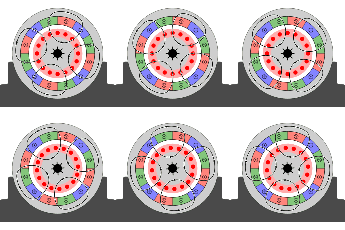
There are two pairs of electromagnet coils present in the motor, which is energized in turn by an AC supply. The two red coils are wired in series and energized together. Since it’s an AC motor, the current in each coil doesn’t switch on and off abruptly, but instead rises and falls smoothly in the shape of a sine wave. As the coils are energized, the magnetic field they produce between them induces an electric current in the rotor. This current produces its own magnetic field, which tries to oppose the thing that caused it (the magnetic field from the outer coils). The interaction between the two fields causes the rotor to turn, dragging it around inside the motor. The rotating magnetic field makes the rotor spin in the same direction, but here is the catch: it never quite keeps up. The rotor always lags a little behind the field, typically by about 1 to 5 percent. This lag is called slip, and it is not a flaw. If the rotor ever did match the field exactly, it would no longer cut across any changing magnetic flux, no current would be induced, and the rotor would stop being pushed at all. A small amount of slip is precisely what keeps an induction motor turning, which is also why it is known as an asynchronous motor. And that, dear reader, is how an induction motor gets the job done!