Table of Contents (click to expand)
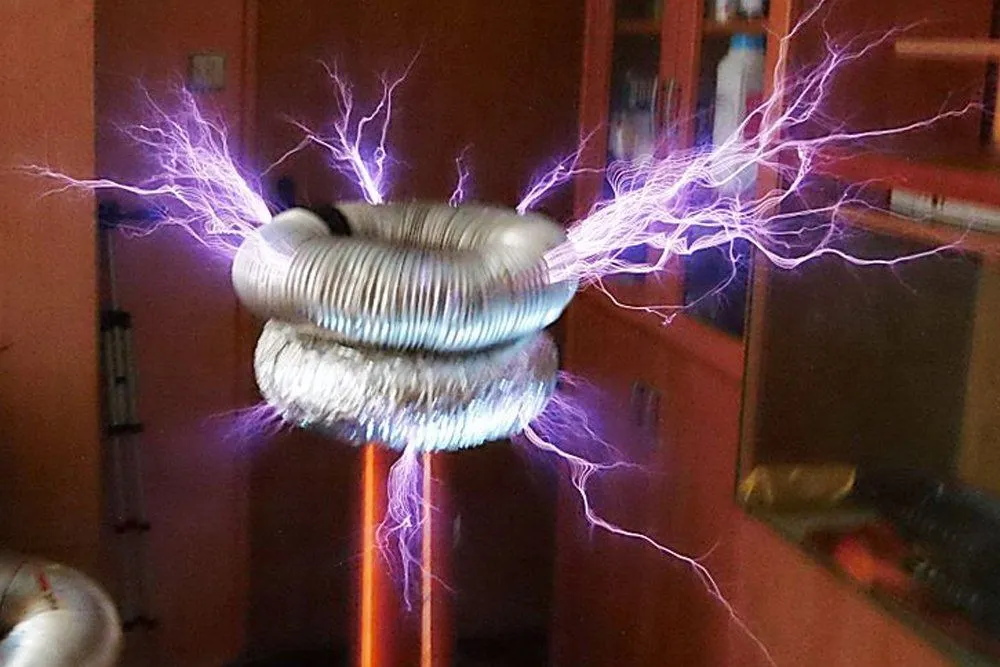
A Tesla coil is an air-core, double-tuned resonant transformer patented by Nikola Tesla in 1891. It uses LC resonance to step a few hundred volts of AC input up to hundreds of thousands—or, in the largest coils, millions—of volts at radio frequencies, producing the long, branching electrical arcs it’s famous for. Tesla designed it to research wireless power transmission; today it’s mostly used in education, entertainment, and historically in early radio and spark-gap transmitters.
The term Tesla coil inherently contains an element of genius within it. This technological wonder prides itself in being named after one of the most prolific and mysterious scientists in history—Nikola Tesla. Nikola Tesla is credited as the pioneer who championed the use of Alternating Current (A.C.) and has a long list of other inventions under his belt that have truly transformed the world. He patented the coil that now bears his name in 1891. However, there was one idea that Tesla was simply obsessed with—the free delivery and transmission of wireless energy. Sounds crazy, right? Even so, that’s what Tesla set out to do with his Tesla Coil.
Operation Of The Tesla Coil
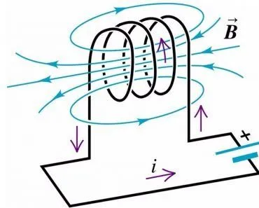
To put this in a nutshell, a Tesla Coil is a radio frequency oscillator that drives a double-tuned resonant transformer to produce high voltages with low currents. Now, to better understand what a radio frequency oscillator is, let’s take one further step back to first understand an electronic oscillator. An electronic oscillator is primarily an electronic circuit that produces an oscillating electrical signal, which is often a sine wave or a square wave. Oscillators convert direct current from a power supply to an alternating current signal. An electronic oscillator that produces signals in the radio frequency range (100kHz to 100GHz) is called a radio frequency oscillator.
A resonant transformer works on the concept of resonant inductive coupling, where the secondary coil in the transformer is loosely coupled, so it resonates. The special aspect of the resonant transformer is that either one or both the circuits present in the transformer consists of a capacitor connected in parallel to it. This coupling of the transformer circuit and the capacitor turns it into a tuning circuit. A tuning circuit or LC circuit is used either for generating signals at a particular frequency or picking out a signal at a particular frequency from a more complex signal, which is also known as a bandpass filter.
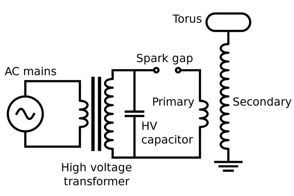
Whether you compare the first patented model or the more modern ones, there is one commonality that you will find in all of them—the spark gap. The functionality of the spark gap is to excite the oscillated electrical signal from the resonant circuit. The unique design of the coil ensures that there are low resistive energy losses at high voltages, which the Tesla Coil produces.
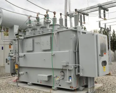
Now that we understand the different components of such a coil, we can delve into the operation of the Tesla Coil in its entirety. First, an upstream supply transformer charges the primary capacitor to a high level, typically 5 to 30 kilovolts—enough to make the primary spark gap break down and ionize. The capacitor in the circuit forms a tuned LC circuit with the primary winding L1 of the apparatus, and the spark gap acts as a fast switch that briefly “closes” the primary loop. Once the gap is conducting, the primary LC circuit rings at its resonant frequency, and energy couples into the secondary coil (L2). The secondary, also tuned to the same frequency, builds up the final output—often hundreds of thousands of volts in a hobby coil, and several million volts in the largest demonstration coils.
Mathematical Nuances Of The Tesla Coil
There are three important mathematical nuances or foundations upon which the operation of the Tesla Coil is built. The two main features are the oscillating frequency and the output voltage. First, let’s take a look at the oscillating frequency. To produce the largest amount of voltage possible from a Tesla Coil, it must be ensured that the primary and secondary circuits of the resonance transformer are tuned to resonate with each other. The resonant frequencies of the primary and secondary circuits are defined by f1 and f2. Usually, the secondary circuit frequency (f2) cannot be adjusted. However, the primary can be adjusted with the help of a tap. The conditions for resonance are given below:
![]() Unlike conventional transformers, the output voltage of the resonance transformer is not directly proportional to the number-of-turns ratio, as in the case of an ordinary transformer. It can be calculated through the conservation of energy. When the cycle begins, and the spark starts all of the energy from the primary circuit, W1 is stored in the capacitor C1. If V1 is the voltage at which the spark gap breaks down, which is usually close to the peak output voltage of the supply transformer T, this energy is:
Unlike conventional transformers, the output voltage of the resonance transformer is not directly proportional to the number-of-turns ratio, as in the case of an ordinary transformer. It can be calculated through the conservation of energy. When the cycle begins, and the spark starts all of the energy from the primary circuit, W1 is stored in the capacitor C1. If V1 is the voltage at which the spark gap breaks down, which is usually close to the peak output voltage of the supply transformer T, this energy is:
![]()
Over a few cycles of resonant ringing, this energy transfers from the primary into the secondary circuit (in a well-tuned coil with sufficiently loose coupling, essentially all of it can move across in a small number of cycles). At the peak energy level of the system, the voltage on the secondary side is V2, the energy stored is W2, and the capacitance of the secondary circuit (mostly the small self-capacitance of the secondary coil and toroid) is C2. Assuming no losses, W1 and W2 will be equal, so V2 = V1 × √(C1/C2). Because C2 is far smaller than C1, the secondary voltage ends up enormously higher than the primary voltage—that’s how a coil charged to 20 kV can produce a discharge in the hundreds of kilovolts. This is the same principle Tesla hoped to use for wireless power transmission, but in practice the energy that radiates outward as electromagnetic waves spreads out quickly and most of it never makes it to a distant receiver.