Table of Contents (click to expand)
Electric power distribution is the final stage of the electrical power system: it carries electricity from the high-voltage transmission grid to your home or business. It has two parts. Primary distribution moves power at 4 to 35 kilovolts to neighborhoods, and secondary distribution steps that down to the 120/240 volts (US) or 230 volts (UK and most of Europe) that wall outlets actually use.
Electric power distribution is the final stage of an electrical power system, the part that actually puts electricity on your wall outlet. Its job is to carry power from the high-voltage transmission network to every kind of customer, from a single house to a hospital to a factory floor. The distribution side of the grid has two main subsections: primary distribution (the medium-voltage lines that fan out from a substation) and secondary distribution (the low-voltage drops that feed individual buildings). Before we get into the nuts and bolts, let’s look at how distribution actually came to exist, because it explains why modern grids are wired the way they are.
History
The need for electric power distribution only emerged in the 1880s, once electricity was being produced by well-established industries. Before that, electricity was generated only where it was needed. The need for, or reach of, electricity was minimal before the 1880s, which sounds odd in our power-driven modern world. The first electric power distribution systems went up in the US and Europe to light city streets. The arc lamps used for street lighting were wired many in series, so the circuit voltage typically ran into the several-thousand-volt range (Brush’s New York systems reached up to about 10 kV), while incandescent lamps for indoor use ran on much lower voltages around 100 to 110 V. Over time, arc lighting stayed in public spaces while incandescent lighting moved into people’s homes.
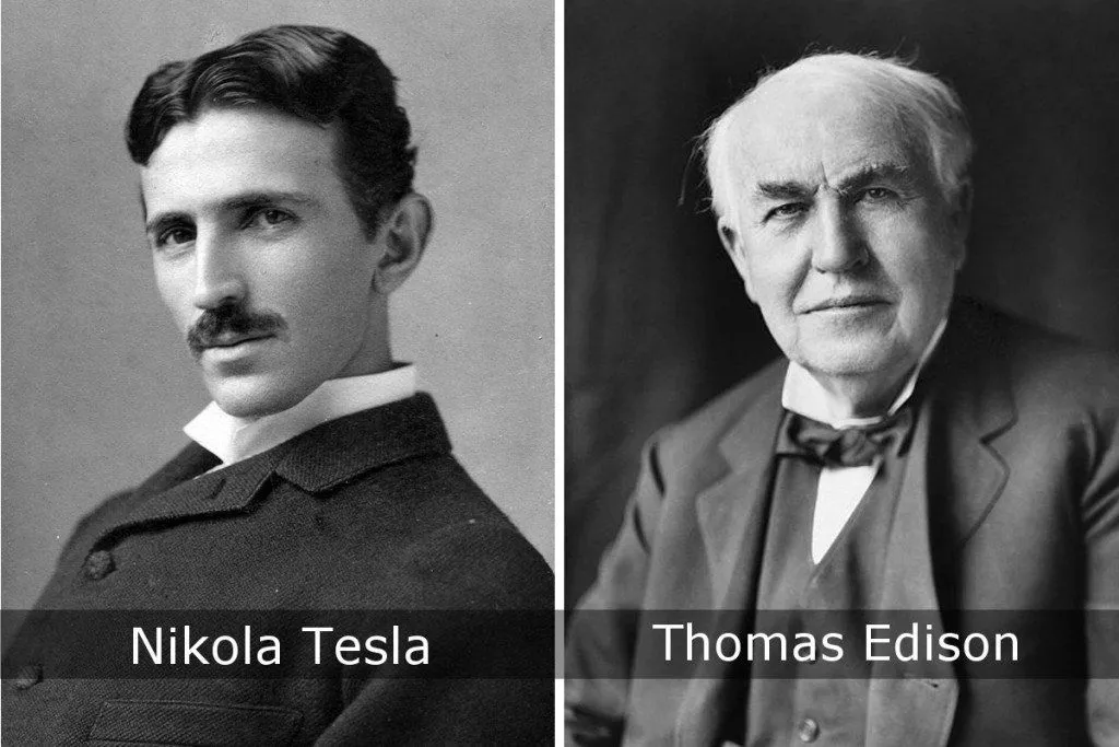
Because arc lighting ran at such high voltages, a single generating station could supply a long string of lamps over surprisingly long circuits (Brush’s system in Brooklyn ran arc lamps on a circuit roughly 14 km, or 8.7 mi, long). Each doubling of the voltage lets the same size cable carry the same power four times as far for a given power loss. Direct current indoor incandescent lighting systems, such as the Edison Pearl Street Station that opened in lower Manhattan in 1882, had a much harder time of it. Pearl Street ran at 110 volts DC end-to-end, from the generators to the lamps, so its service area only stretched about half a mile (around 0.8 km) from the plant. Pushing further would have meant impractically thick (and expensive) copper conductors.
That mismatch (high voltage is great for moving power over distance, low voltage is what customers actually want) is exactly the problem the transformer solved in the mid-1880s. The first practical closed-core AC transformer was built in 1885 by the Hungarian ZBD team (Bláthy, Déri and Zipernowsky) at the Ganz Works, and William Stanley refined the design for George Westinghouse, demonstrating the first full AC distribution system in Great Barrington, Massachusetts in March 1886. With transformers, you could step voltage up for transmission and back down at the customer’s end, instead of building the whole grid around one fixed voltage. That single change is what made modern, wide-area electricity distribution possible.
Primary Distribution
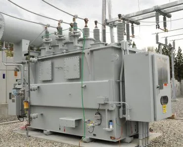
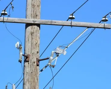
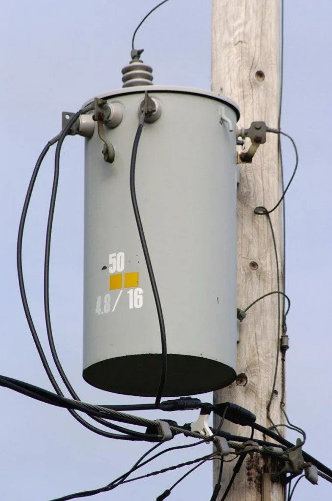
Primary distribution is the medium-voltage layer that fans out from a distribution substation, with pole-mounted or pad-mounted transformers sprinkled along the way to feed local clusters of customers. In North America, primary distribution voltages typically sit between 4 and 35 kilovolts (kV), with 4.16 kV, 12.47 kV, 13.2 kV and 34.5 kV among the most common values; large industrial customers can tap the higher end of that range directly, while everyone else is served through a step-down transformer. The layout of those primary lines comes in two main flavors, radial and network (with a loop or ring layout as a common variant). A radial feeder is like a tree: a single path runs from the substation out to the customer. A network or ring layout has multiple parallel paths to the source. Radial feeders are the workhorse of rural and suburban areas because they are simple and cheap, while denser, load-sensitive areas (downtown cores, hospitals, data centers) lean on networked layouts for redundancy. Modern radial feeders are not as fragile as they sound either, since most include tie switches and backup paths that can reroute power when a fault occurs.
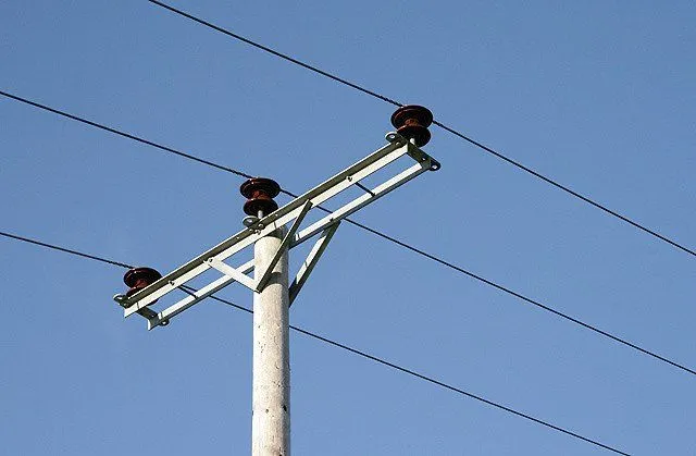
If we zoom in on how those radial feeders are laid out for rural electrification, one pattern stands out: distribution voltages are usually higher in rural areas than in cities. The reason is geometric. A higher voltage means lower current for the same power, which means thinner conductors and longer spans between supports, so utilities can cover miles of farmland with fewer poles. Many of those long rural spans use galvanized-steel-reinforced aluminum conductor (ACSR), which is strong enough to carry the line over long distances without the need for too many distribution poles.
Secondary Distribution
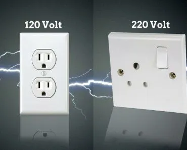
Electricity is not characterized by voltage and current alone. There is a third property that matters at the wall outlet: frequency. Grids around the world settle on one of two values, either 50 Hz or 60 Hz, and the choice is mostly a historical accident that then locked in everything downstream. The secondary side of the grid delivers this power to homes as single-phase AC. In North America, what comes into a house is actually a 240 V split-phase service with a center-tapped neutral, which gives you two 120 V legs for lights and outlets and a 240 V combination for big appliances like dryers and electric ranges. Hook a 120 V outlet up to an oscilloscope and you see a 60 Hz sine wave swinging between roughly −170 V and +170 V, which works out to 120 V RMS (120 × √2 ≈ 170 V peak).
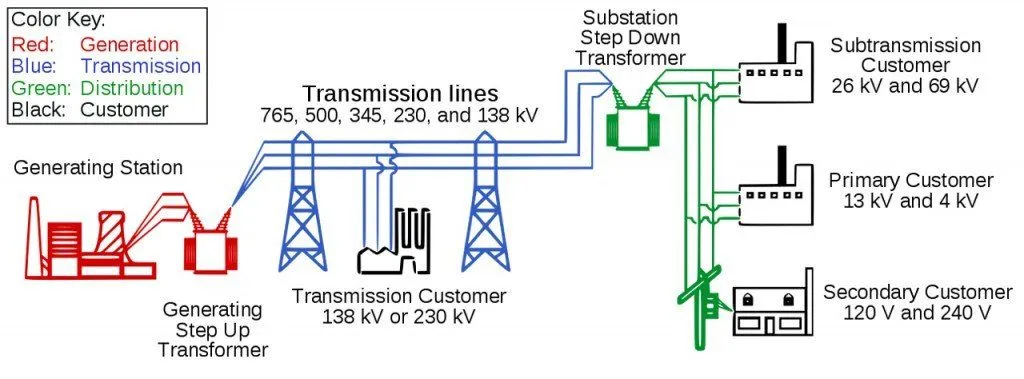
The picture looks different elsewhere. Most of Europe, the UK, Australia and large parts of the rest of the world standardized on 230 V at 50 Hz single-phase for homes, with a 400 V three-phase supply available for bigger loads. Three-phase power is more efficient per kilogram of copper and is much better at running large motors, which is why some European homes have three-phase service feeding things like electric ovens, instantaneous water heaters or EV chargers. Wherever you live, a ground connection (also called earthing) is provided for both the customer’s installation and the utility’s own equipment. Its job is to limit the voltage that could develop if a high-voltage conductor falls onto a lower-voltage one (overhead lines are stacked with the higher voltages at the top), or if a distribution transformer fails internally. Put it all together and you can see why distributing electricity is no small feat. It requires a tremendous amount of engineering and a clear understanding of the geography being powered.
References (click to expand)
- Electricity explained: Delivery to consumers. U.S. Energy Information Administration (EIA).
- Illustrated Glossary: Substations. Occupational Safety and Health Administration (OSHA).
- Milestones: Pearl Street Station, 1882. Engineering and Technology History Wiki (IEEE).
- Electric transmission. Encyclopaedia Britannica.
- What is the difference between electricity transmission and distribution? National Grid.
- Electric power distribution. Wikipedia.