Table of Contents (click to expand)
A Carnot engine is an idealized heat engine that runs the Carnot cycle: two reversible isothermal steps and two reversible adiabatic steps that move heat from a hot reservoir to a cold one. It marks the theoretical efficiency ceiling for any engine working between the same two reservoirs, equal to 1 − Tc/Th, with both temperatures in Kelvin. No real engine can beat it.
When we use a machine, we want to get as much out of it as we can. So it’s no wonder that the early steam engines frustrated the engineers who ran them. Thomas Newcomen’s engine of 1712, the first commercially successful design, wasted the overwhelming majority of the heat from the coal it burned. When James Watt added his separate condenser in 1765 (patented in 1769), he cut that fuel waste by roughly 75%, yet even his improved engine threw away most of its energy. The race was on to squeeze more work out of every lump of coal. The steam engine was one of the most important innovations that helped “drive” the Industrial Revolution, so improving its efficiency was an essential goal for the scientists of that era.
In the year 1824, Nicolas Léonard Sadi Carnot, a French military engineer, proposed a theory that was quite ground-breaking in defining the thermodynamics of a heat engine. He visualized a “perfect” heat engine, also known as Carnot’s Engine or Carnot’s Cycle, with the greatest possible efficiency. In that engine, heat moved from a hot reservoir to a cold reservoir through a cylinder-piston assembly, converting some of the heat to work.
As it was a “perfect” engine, there was no waste of heat in friction or any loss in changing the temperature of the other parts of the engine. He proposed that such an engine could not achieve 100% efficiency and that there would always be an upper limit to the efficiency it could achieve. His theorem stated: No engine operating between two heat reservoirs can be more efficient than a Carnot engine operating between those same reservoirs.
Carnot’s Cycle
To understand it in detail, let’s look at the way Carnot’s Cycle is structured. A prior understanding of the laws of thermodynamics and entropy is helpful in order to follow the concepts below.
Carnot’s Cycle is assumed to be a fully reversible process. This means it can be run forward or backward and always returns to its exact starting state once the cycle is complete, with no friction and no wasted heat. Reversible does not mean spontaneous, though: the engine still does work on its surroundings during the expansion strokes, and the surroundings must do work back on the gas during the compression strokes. A Carnot Cycle is divided into 4 main steps:
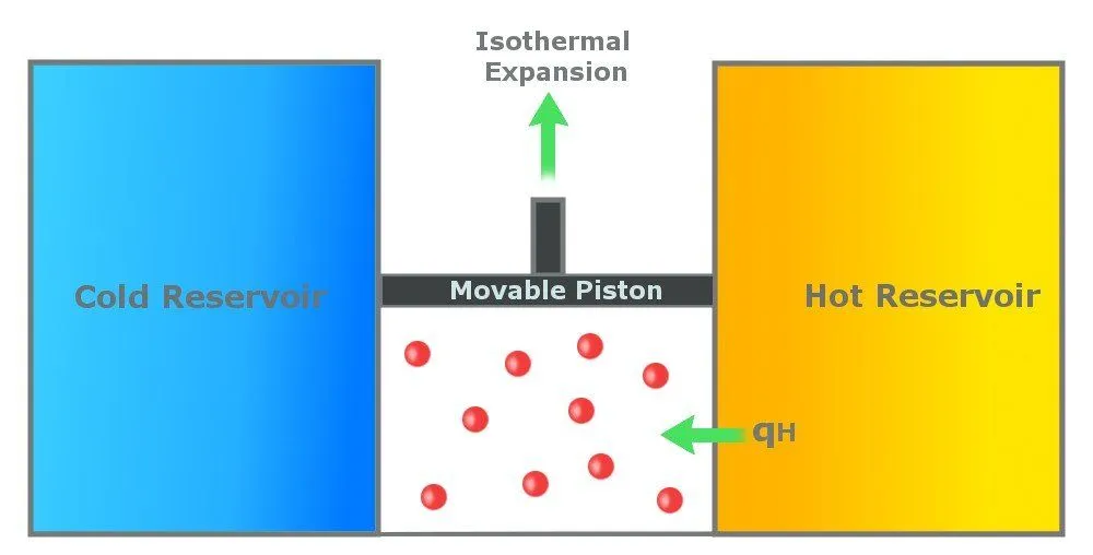
Step 1: Reversible Isothermal Gas Expansion
In the first step, the gas in the cylinder absorbs Qh amount of heat from the hot reservoir, which is at a temperature Th. The gas expands isothermally at Th. An isothermal process is a process in which the temperature remains constant throughout the process. In this step, the temperature of the gas remains constant at Th. The gas expands due to the energy it receives and does work on the surroundings.
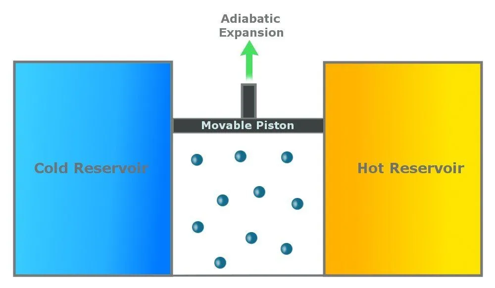
 Step 2: Reversible Adiabatic Gas Expansion
An adiabatic process is one that is thermally insulated and does not lose heat. In the second step, the gas continues to expand and does work on the surroundings. The cylinder does not lose heat (as it is thermally insulated), and the gas expands (to do work), so the temperature of the gas drops to Tc.
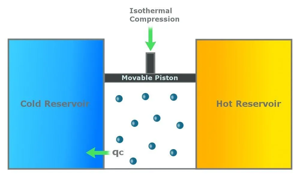
 Step 3: Reversible Isothermal Gas Compression
In this step, the cylinder loses heat (Qc) to the cold reservoir. This step is again isothermal, which means that it happens at a constant temperature of Tc. Due to the heat loss, the gas compresses, pushing the piston down.
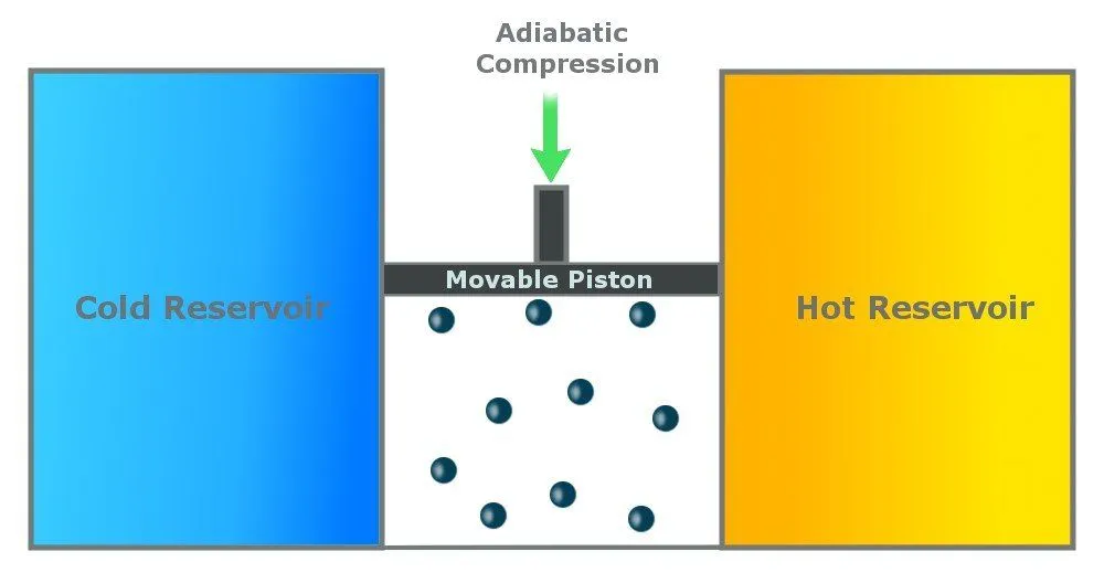
 Step 4: Reversible Adiabatic Gas Compression
In the last step, the cylinder is again insulated from the environment, and there is no heat exchange. The environment does work on the piston, and the piston moves back to compress the gas. The gas again attains the temperature of Th and retains its original state.
 Carnot Cycle Efficiency
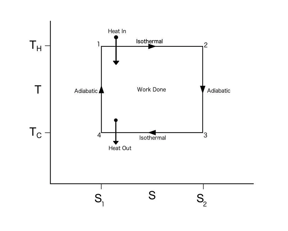
To calculate the efficiency of a Carnot Cycle, we must look at the heat flow between the reservoirs and the work done by the system. It can also be calculated using the entropy of the system. As this process is reversible, there is no generation of entropy by the system. In other words, the total entropy of the system is conserved. Heat flows out from the hot reservoir and flows to the cold reservoir. Thus, the entropy, ΔS, is taken from the hot reservoir and given to the cold reservoir.
This means Qh, which is the heat taken from the hot reservoir, equals ThΔS, and the heat given to the cold reservoir Qc equals TcΔS.
The work done by the engine = Qh – Qc = (Th – Tc)ΔS
The efficiency of any system is defined as the work done divided by energy input. Thus, the efficiency of the Carnot Cycle is:
Efficiency = (Qh – Qc) / Qh = (Th – Tc)ΔS / ThΔS = (1 – Tc/Th)
Remember, there can be no heat flow between the reservoirs if there is no difference between the temperatures of the two reservoirs. This equation proved that the efficiency of any engine cannot be 1 (or 100%). The ideal efficiency of a heat engine will always depend on the temperatures of the heat reservoirs.
One catch with this formula: the temperatures must be in Kelvin, not Celsius or Fahrenheit. Let’s try a quick example. Say steam enters at 200 °C (392 °F) and is exhausted at 100 °C (212 °F). First convert to Kelvin by adding 273.15: Th = 473.15 K and Tc = 373.15 K. The Carnot efficiency is then 1 − (373.15 / 473.15) = 0.211, or about 21%. That is the best this engine could ever do, and a real engine, with its friction and heat leaks, would fall well short of it. Notice the lesson built into the formula: the only way to push efficiency higher is to widen the gap between the hot and cold reservoirs, by running the hot side hotter or the cold side colder.
Carnot Cycle PV Diagram
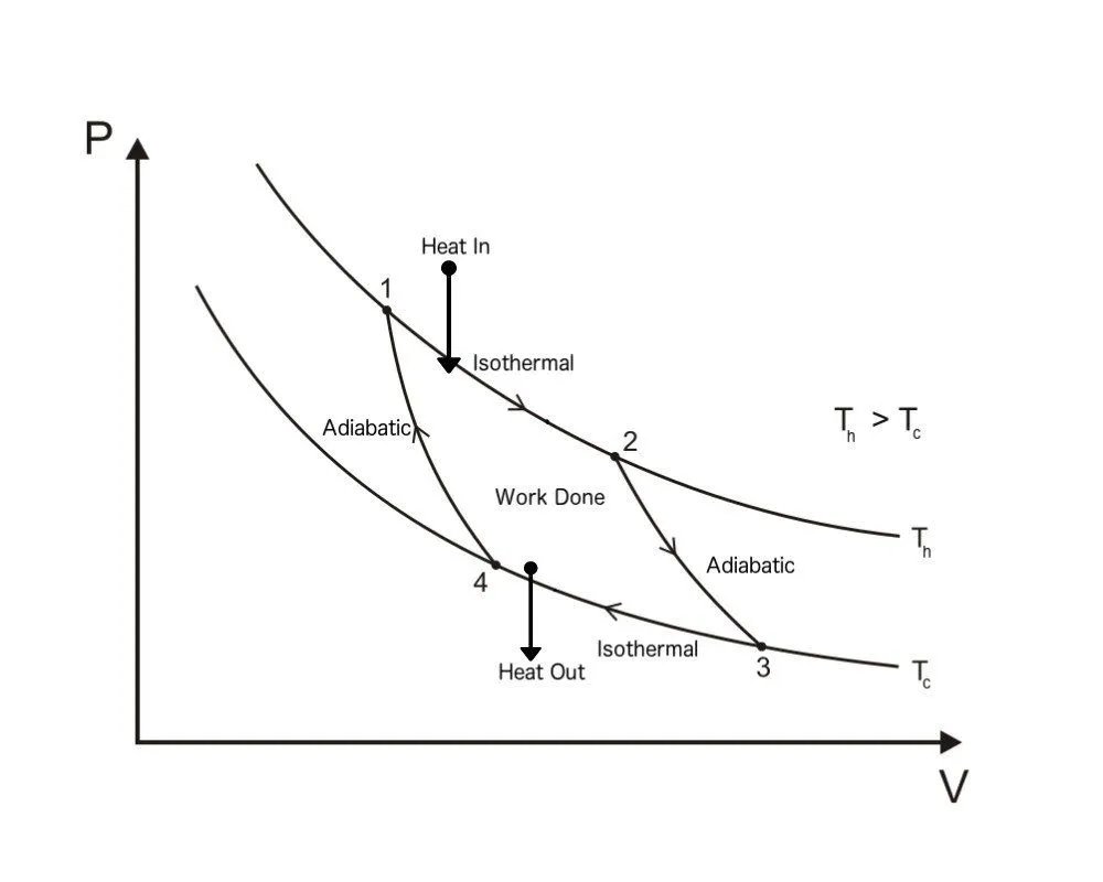
A Carnot Cycle, when plotted on a PV (Pressure-Volume) plot, looks as shown below. The work done by the engine is represented by the area bounded by the complete path of the PV plot.
Carnot Cycle TS Diagram
A Carnot Cycle, when plotted on a TS (Temperature-Entropy) plot, looks as shown below. Here again, the work done by the engine is represented by the area bounded by the complete path of the TS plot.